The process of Reverse Engineering is usually needed when there are no drawings available for an existing component, but full CAD data is needed. This can apply to some re-shoring projects, where the overseas plastic processing company designed the component and manufactured the tooling. In other cases, drawings may simply have been mislaid. The process involves the complete dimensional analysis and digitisation of the existing component, either by contact measurement or through the use of a laser scanner. A three dimensional CAD drawing can then be used to manufacture new tooling, or sometimes to aid in the design of a new and improved version of the original design.
A typical example would be a recent project to reverse engineer an automotive cover for JLR. The below images were generated during the process:
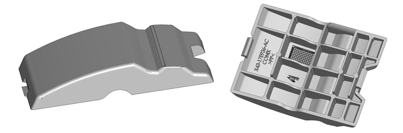
A more detailed case study on the reverse engineering of a hydraulic oil filling system can be read below. In this instance, our client not only wanted to produce accurate drawings for an existing component, but they also wanted to make improvements to the original design:
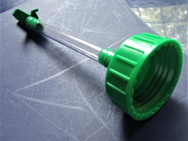
The brief was to replace an existing method for topping up an under-bonnet hydraulic oil reservoir. This was traditionally done by removing the sealing cap from a plastic bottle containing the oil, then inserting a bung into the bottle’s neck that incorporated a silicone tube with an end probe that was inserted into the reservoir.
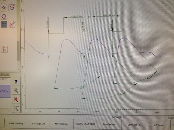
Stage one was to accurately measure the ‘male’ thread form of the bottle, which was non-uniform rather than matching a known standard. This was done using a Contour Measurement Machine and used to produce a circular digital rendering of the thread. Specialist software then generated a mirror thread, i.e. as a female form that could be incorporated into the new assembly.
Stage two involved the measurement and digital rendering of the original solid bottle cap, as well as the end probe.
Stage three required the now completely modelled old components to be combined into a new cap design with an integrated hose-tail section, the latter copied from the end probe. A new internal sealing ring was also designed and added, this to prevent leakage when the oil bottle is inverted.
Stage four involved the selection of suitable plastic material, in this case, HDPE. Allowances were then made for material shrinkage rates, as well as the required tolerances for thread meshing and sealing surfaces.
Stage five required production tooling to be manufactured for all components.
Stage six was the final stage, our sister company LVS Small Plastic Parts, initially sampling the tools, before moving to mass production and assembly.